Product Description
Product Description
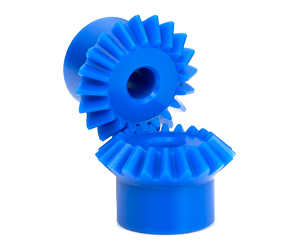
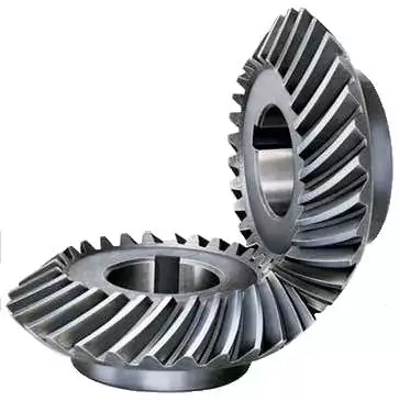
Drive Machining Custom Cog-Wheel Toothed Cylindrical reduction miter Straight Bevel Gear
| Item | Customized machined machining gears | |
| Process | CNC machining,CNC milling, cnc lathe machining | |
| material | steel, stainless steel, carbon steel,brass,C360 brass copper, aluminum 7075,7068 brass,C360 brass copper, aluminum Nylon, PA66, NYLON , ABS, PP,PC,PE,POM,PVC,PU,TPR,TPE,TPU,PA,PET,HDPE,PMMA etc | |
| Quality Control | ISO9001 and ISO14001 | |
| Dimension bore tolerances | -/+0.01mm | |
| Quality standard | AGMA, JIS, DIN | |
| Surface treatment | Blackening, plated, anodizing, hard anodizing etc | |
| Gear hardness | 30 to 60 H.R.C | |
| Size/Color | Gears and parts dimensions are according to drawings from customer, and colors are customized | |
| Surface treatment | Polished or matte surface, painting, texture, vacuum aluminizing and can be stamped with logo etc. | |
| Dimensions Tolerance | ±0.01mm or more precise | |
| Samples confirmation and approval | samples shipped for confirmation and shipping cost paid by customers | |
| Package | Inner clear plastic bag/outside carton/wooden pallets/ or any other special package as per customer’s requirements. | |
| Delivery Time | Total takes 2~~8weeks usually | |
| Shipping |
Usual FEDEX, UPS, DHL, TNT, EMS or base on customer’s requirement. |
Production management:
1. The workers are trained to inspect the gears and notice any defect in production in time.
2. QC will check 1pcs every 100pcs in CNC machining, and gears will meet all dimension tolerances.
3. Gears will be inspected at every step, and gears will be inspected before shipment, and all inspection records will be kept in our factory for 3 years.
4. Our sales will send you pictures at every gears production steps, and you will know the detailed production status, and you can notice any possibility of mistake, for our sales, QC and workers are keeping close watch on all production.
5. You will feel us working very carefully to assure the quality and easy to work with,
6. we cherish every inquiry, every opportunity to make gears and parts and cherish every customer.
QUALITY CONTROL PROCESS:
1) Inspecting the raw material –IQC)
2) Checking the details before the production line operated
3) Have full inspection and routing inspection during mass production—In process quality control (IPQC)
4) Checking the gears after production finished—- (FQC)
5) Checking the gears after they are finished—–Outgoing quality control (OQC)
Service:
1. Molds designs as per customers’ gears drawing;
2. Submitting molds drawings to customers to review and confirm before mols production.
3. Providing samples with whole dimensions and cosmetic inspection report, material certification to customers.
4. Providing inspection report of important dimensions and cosmetic in batches parts.
Packing and shipment:
1. Gears are well and carefully packed in PP bags in CTNS, strong enough for express shipping, air shipment or sea shipment.
2. Air shipment, sea shipment or shipment by DHL, UPS, FedEx or TNT are availabe.
3. Trade terms: EXW, FOB HangZhou, or CIF
4. All shippings will be carefully arranged and will reach your places fast and safely.
FAQ
Q1: How to guarantee the Quality of gears and parts?
We are ISO 9001:2008 certified factory and we have the integrated system for industrial parts quality control. We have IQC (incoming quality control),
IPQCS (in process quality control section), FQC (final quality control) and OQC (out-going quality control) to control each process of industrial parts prodution.
Q2: What are the Advantage of your gears and parts?
Our advantage is the competitive and reasonable prices, fast delivery and high quality. Our eployees are responsible-oriented, friendly-oriented,and dilient-oriented.
Our industrial parts products are featured by strict tolerance, smooth finish and long-life performance.
Q3: what are our machining equipments?
Our machining equipments include plasticn injection machinies, CNC milling machines, CNC turning machines, stamping machines, hobbing machines, automatic lathe machines, tapping machines, grinding machines, cutting machines and so on.
Q4: What shipping ways do you use?
Generally, we will use UPS DHL or FEDEX and sea shipping
5: What materials can you process?
For plastic injection gears and parts, the materials are Nylon, PA66, NYLON with 30% glass fibre, ABS, PP,PC,PE,POM,PVC,PU,TPR,TPE,TPU,PA,PET,HDPE,PMMA etc.
For metal and machining gears and parts, the materials are brass, bronze, copper, stainless steel, steel, aluminum, titanium plastic etc.
Q6: How long is the Delivery for Your gears and parts?
Generally , it will take us 15 working days for injection or machining, and we will try to shorten our lead time.
/* March 10, 2571 17:59:20 */!function(){function s(e,r){var a,o={};try{e&&e.split(“,”).forEach(function(e,t){e&&(a=e.match(/(.*?):(.*)$/))&&1
| Application: | Motor, Electric Cars, Machinery, Toy, Agricultural Machinery, Car |
|---|---|
| Hardness: | Hardened Tooth Surface |
| Gear Position: | External Gear |
| Manufacturing Method: | Cut Gear |
| Toothed Portion Shape: | Curved Gear |
| Material: | Stainless Steel |
| Samples: |
US$ 10/Piece
1 Piece(Min.Order) | |
|---|
| Customization: |
Available
| Customized Request |
|---|
Can miter gears be used in high-torque applications?
Miter gears can indeed be used in high-torque applications, although there are certain considerations to keep in mind. Here’s a detailed explanation:
Miter gears are capable of transmitting significant amounts of torque due to their tooth design and load distribution characteristics. The interlocking tooth design of miter gears allows for efficient torque transfer between mating gears, minimizing power loss. Additionally, the load distribution across multiple teeth helps to distribute the torque and reduce stress concentrations on individual teeth.
However, the suitability of miter gears for high-torque applications depends on several factors:
1. Tooth Design:
The tooth design of miter gears plays a crucial role in their torque-carrying capacity. Spiral bevel gears, with their curved teeth, are particularly well-suited for high-torque applications. The curved tooth profile allows for increased contact area and smoother engagement, resulting in improved torque transmission and higher load capacity compared to straight bevel gears.
2. Gear Material and Hardness:
The material and hardness of the miter gears are important considerations for high-torque applications. The gears should be made from materials with high strength and wear resistance, such as alloy steels. Proper heat treatment and surface hardening techniques can further enhance the gear’s ability to withstand high torque loads and minimize wear.
3. Lubrication and Cooling:
Effective lubrication is essential for high-torque applications to reduce friction and heat generation. Lubricants help to minimize wear and ensure smooth gear operation. In some cases, additional cooling mechanisms, such as forced-air or liquid cooling, may be required to dissipate heat generated during high-torque operation.
4. Gear Size and Diameter:
The size and diameter of the miter gears can impact their torque-carrying capacity. Larger gears generally have larger contact areas and can handle higher torques. However, it’s important to consider the available space and operating constraints when selecting the gear size.
5. Backlash Control:
Backlash, the clearance between mating teeth, can affect the smoothness and accuracy of torque transmission. In high-torque applications, maintaining proper backlash control becomes even more critical to prevent any unwanted movement or play that could impact performance and reliability.
By considering these factors, engineers can select miter gears that are suitable for high-torque applications. It’s important to consult gear manufacturers and design experts to ensure the gears are properly sized, designed, and manufactured to handle the specific torque requirements of the application.

How do you calculate the gear ratio in a miter gear assembly?
The gear ratio in a miter gear assembly can be calculated by considering the number of teeth on the gears involved. Here’s a step-by-step explanation:
1. Determine the Number of Teeth:
Identify the number of teeth on both the driving gear (input gear) and the driven gear (output gear) in the miter gear assembly. The number of teeth can usually be found in the gear specifications or by physically counting the teeth.
2. Calculate the Gear Ratio:
To calculate the gear ratio, divide the number of teeth on the driven gear (output gear) by the number of teeth on the driving gear (input gear). The formula for calculating the gear ratio is:
Gear Ratio = Number of Teeth on Driven Gear / Number of Teeth on Driving Gear
3. Simplify the Ratio (Optional):
If the resulting gear ratio is a fraction, it can be simplified to its simplest form. Divide both the numerator and the denominator by their greatest common divisor to simplify the ratio.
4. Interpret the Gear Ratio:
The gear ratio indicates the relationship between the rotational speed or angular velocity of the driving gear and the driven gear. It represents how many times the driven gear rotates for each rotation of the driving gear. For example, a gear ratio of 2:1 means that the driven gear rotates twice for every rotation of the driving gear.
5. Consider the Significance:
The gear ratio has practical implications in determining the mechanical advantage and speed reduction/amplification in a miter gear assembly. A gear ratio greater than 1 indicates a speed reduction and increased torque, while a gear ratio less than 1 indicates a speed amplification and decreased torque.
In summary, the gear ratio in a miter gear assembly is calculated by dividing the number of teeth on the driven gear by the number of teeth on the driving gear. This ratio represents the relationship between the rotational speeds of the gears and provides insights into the mechanical advantage and speed transformation in the gear assembly.
What industries commonly use miter gears in their applications?
Miter gears are widely employed in various industries due to their unique characteristics and advantages. Here are some industries that commonly use miter gears in their applications:
1. Automotive Industry:
In the automotive industry, miter gears are commonly found in differentials. Differentials are responsible for distributing torque between the wheels, allowing them to rotate at different speeds during cornering. Miter gears play a crucial role in transmitting power from the driveshaft to the wheels at a right angle, enabling efficient torque distribution.
2. Robotics:
Miter gears are extensively used in robotics for transmitting power and motion between intersecting shafts. Robots often require changes in the direction of rotation, and miter gears enable smooth and efficient redirection of power at a 90-degree angle. They find applications in robotic arms, grippers, and various other robotic mechanisms.
3. Manufacturing and Machinery:
Miter gears are utilized in manufacturing and machinery for power transmission and speed adjustment. They find applications in various types of machinery such as printing machinery, woodworking tools, and conveyor systems. Miter gears allow for efficient transmission of power between perpendicular axes, enabling the precise and controlled operation of these machines.
4. Aerospace and Defense:
In the aerospace and defense industries, miter gears are employed in various applications. They are used in aircraft engines, navigation systems, weapon systems, and other critical mechanisms. Miter gears provide reliable power transmission and direction changes in space-constrained environments.
5. Marine Industry:
Miter gears find applications in the marine industry for transmitting power and motion between intersecting shafts on boats, ships, and other watercraft. They are used in propulsion systems, steering mechanisms, and other marine equipment that require changes in shaft direction.
6. Camera and Optics:
Miter gears are utilized in camera lenses and other optical equipment to change the direction of rotational motion. They enable precise adjustment of focus, zoom, and other lens functions. Miter gears help ensure accurate alignment and smooth operation in optical systems.
7. Other Applications:
In addition to the industries mentioned above, miter gears are also found in applications such as mechanical clocks, medical devices, agricultural machinery, and more. Their versatility and ability to transmit power at a right angle make them suitable for diverse mechanical systems.
In summary, miter gears are commonly used in industries such as automotive, robotics, manufacturing and machinery, aerospace and defense, marine, camera and optics, as well as in various other applications. The unique capabilities of miter gears make them valuable for efficient power transmission and direction changes in a wide range of industries and mechanical systems.


editor by CX 2023-12-25