Product Description
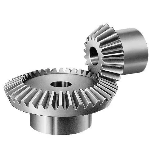
A right-angle gearbox with a gear ratio of 1:1 is called a miter gearbox. The high end of bevel gearbox ratios rarely exceeds 5:1 due to the size of the larger bevel gear. However, our high ratio right angle gearboxes are unique: these heavy-duty boxes incorporate additional gearing to accomplish higher ratios than can be found in other right angle gearboxes. Our High-Performance Right-Angle Gearboxes are offered in numerous configurations to meet your application requirements.
Shaft to Shaft Bevel and Bevel-T Gearboxes provide outputs at 90° from the input and utilize a single, T-shaped shaft that passes through the entire unit, with both ends rotating in the same direction simultaneously. Counter-rotating Bevel T gearboxes are also available.
How Does A Compact Bevel Gearbox Work?
Compact Cubic Gearboxes Videos For Customers Orders
* Malaysia customers bevel 90 degree gearbox 1:1 ratio at 36567X3, registered Capital 500000CNY) is a leading manufacturer and supplier of Screw Jacks (Mechanical Actuators), Bevel Gearboxes, Lifting Systems, Electric Linear Actuators, Gearmotors and Speed Reducers, and Others Linear Motion and Power Transmission Products in China. We are Alibaba, Made-In-China and SGS (Serial NO.: QIP-ASI192186) audited manufacturer and supplier. We also have a strict quality system, with senior engineers, experienced skilled workers and practiced sales teams, we consistently provide the high quality equipments to meet the customers electro-mechanical actuation, lifting and positioning needs. CHINAMFG Industry guarantees quality, reliability, performance and value for today’s demanding industrial applications.
Website (English): screw-jacks
Website (English): screw-jacks
Website (Chinese): screw-jacks
| Application: | Motor, Electric Cars, Motorcycle, Machinery, Marine, Agricultural Machinery, Bottle Capping, Food Processing Equipment |
|---|---|
| Function: | Distribution Power, Change Drive Torque, Change Drive Direction, Speed Changing, Speed Reduction, Speed Increase |
| Layout: | Right Angle Drive |
| Hardness: | Hardened Tooth Surface |
| Installation: | Horizontal Type and Vertical Type |
| Step: | Single-Step |
| Customization: |
Available
| Customized Request |
|---|
What is the impact of tooth profile on the efficiency of miter gears?
The tooth profile of miter gears plays a crucial role in determining their efficiency. Miter gears are a type of bevel gears that transmit rotational motion between intersecting shafts. The tooth profile refers to the shape and design of the teeth on the gear.
The efficiency of miter gears is influenced by several factors related to the tooth profile:
- Tooth Shape: The shape of the teeth can significantly affect the efficiency. Ideally, the tooth profile should have a smooth and gradual transition from one tooth to the next. This ensures a uniform distribution of load and minimizes the impact of meshing forces, resulting in higher efficiency.
- Tooth Size: The size of the teeth, including their length and width, can impact the efficiency of miter gears. Larger teeth generally provide better load-carrying capacity and reduce the risk of tooth failure. However, excessively large teeth can increase friction and reduce efficiency.
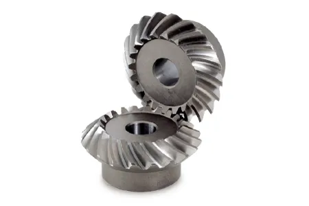
- Tooth Helix Angle: The helix angle of the teeth determines the spiral orientation of the gear. Miter gears with a higher helix angle tend to have smoother meshing action and lower noise levels. This can contribute to improved efficiency by reducing friction and minimizing energy losses.
- Tooth Contact Pattern: The contact pattern between the teeth of miter gears should be optimized for efficient power transmission. Proper tooth contact ensures uniform load distribution and minimizes localized wear. A well-designed tooth profile creates a desirable contact pattern, resulting in higher efficiency.
Therefore, when designing or selecting miter gears, careful consideration should be given to the tooth profile. Optimal tooth shape, size, helix angle, and contact pattern can significantly enhance the efficiency of miter gears, leading to improved overall performance and reduced energy losses.

How do you calculate the gear ratio in a miter gear assembly?
The gear ratio in a miter gear assembly can be calculated by considering the number of teeth on the gears involved. Here’s a step-by-step explanation:
1. Determine the Number of Teeth:
Identify the number of teeth on both the driving gear (input gear) and the driven gear (output gear) in the miter gear assembly. The number of teeth can usually be found in the gear specifications or by physically counting the teeth.
2. Calculate the Gear Ratio:
To calculate the gear ratio, divide the number of teeth on the driven gear (output gear) by the number of teeth on the driving gear (input gear). The formula for calculating the gear ratio is:
Gear Ratio = Number of Teeth on Driven Gear / Number of Teeth on Driving Gear
3. Simplify the Ratio (Optional):
If the resulting gear ratio is a fraction, it can be simplified to its simplest form. Divide both the numerator and the denominator by their greatest common divisor to simplify the ratio.
4. Interpret the Gear Ratio:
The gear ratio indicates the relationship between the rotational speed or angular velocity of the driving gear and the driven gear. It represents how many times the driven gear rotates for each rotation of the driving gear. For example, a gear ratio of 2:1 means that the driven gear rotates twice for every rotation of the driving gear.
5. Consider the Significance:
The gear ratio has practical implications in determining the mechanical advantage and speed reduction/amplification in a miter gear assembly. A gear ratio greater than 1 indicates a speed reduction and increased torque, while a gear ratio less than 1 indicates a speed amplification and decreased torque.
In summary, the gear ratio in a miter gear assembly is calculated by dividing the number of teeth on the driven gear by the number of teeth on the driving gear. This ratio represents the relationship between the rotational speeds of the gears and provides insights into the mechanical advantage and speed transformation in the gear assembly.
What is the purpose of using miter gears in mechanical systems?
Miter gears serve several purposes and offer distinct advantages when used in mechanical systems. Here’s a detailed explanation:
1. Change of Shaft Direction:
One of the primary purposes of using miter gears is to facilitate a change in the direction of shaft rotation. When two miter gears with intersecting shafts are meshed together, they allow the transmission of rotational motion at a 90-degree angle. This enables the redirection of power and torque to a different axis, which can be crucial for the functioning of various mechanical systems.
2. Power Transmission:
Miter gears are designed to efficiently transmit power between intersecting shafts. The meshing of the gear teeth ensures a smooth transfer of rotational energy, enabling the transmission of torque and rotational motion from one shaft to another. This makes miter gears suitable for applications where power needs to be transmitted between perpendicular axes.
3. Speed Reduction or Increase:
By using miter gears with different numbers of teeth or by combining them with other gears, speed reduction or speed increase can be achieved. The gear ratio between the miter gears determines the change in rotational speed. This allows for the adjustment of output speed to match the requirements of the mechanical system, ensuring optimal performance.
4. Compact Design:
Miter gears are known for their compact design, making them valuable in applications where space is limited. The intersecting shafts and the conical shape of the gears allow for efficient power transmission while occupying a small footprint. This compactness is particularly beneficial in devices and systems where size and weight constraints are critical factors.
5. Alignment and Torque Distribution:
Miter gears help maintain proper alignment and torque distribution between intersecting shafts. The gear teeth engagement ensures accurate alignment, which is essential for smooth and efficient operation. Additionally, the equal distribution of torque among the teeth of miter gears helps prevent excessive stress on individual gear teeth, promoting longevity and reliability.
6. Applications:
Miter gears find applications in a wide range of mechanical systems, including:
- Power transmission systems
- Automotive differentials
- Mechanical clocks
- Robotics
- Printing machinery
- Woodworking tools
- Camera lenses
In summary, the purpose of using miter gears in mechanical systems is to facilitate a change in shaft direction, transmit power efficiently, achieve speed reduction or increase, maintain a compact design, and ensure proper alignment and torque distribution. These characteristics make miter gears suitable for various applications, contributing to the functionality and performance of mechanical systems.


editor by CX 2023-11-06