Product Description
1.P roduct Description
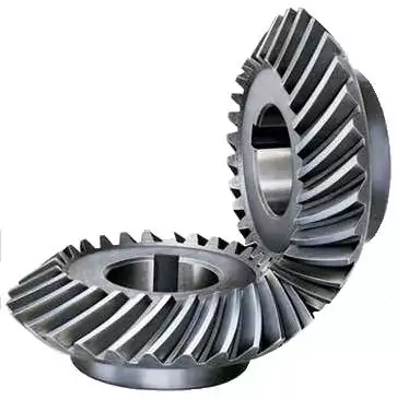
Gear shaft, Herringbone Gear Shaft, Bevel Gear, Eccentric Shaft mainly used on vessel engine, fan internal gear
1.1. Bevel Gear, Pinion Shaft Processing
Gear drawing— Simulation Modelling—Making casting model—Casting— Primary Detection—Rough machining—Hardening Tempering—Semi-finishing machining —Hobbing—Tooth Surface Quenching—Gear grinding—Gear Surface Carburzing—Inspection—Spray Anti-rust Oil—Package—Delivery
Gear Shaft drawing CHECK, Make Forging Mold, Forging Mold Quality Inspection Check, Machine Processing, Check Size\Hardness\Surface Finish and other technical parameters on drawing.
2.2. Bevel Gear Package
Spray anti-rust oil on Herringbone Gear Shaft, Wrap waterproof cloth around Gear Shaft for reducer, Prepare package by shaft shape&weight to choose steel frame, steel support or wooden box etc.
1.3. OEM Customized Pinion Shaft
We supply OEM SERVICE, customized herringbone gear shaft with big module, more than 1tons big weight, more than 3m length, 42CrMo/35CrMo or your specified required material gear shaft.
2.Product Technical info.
| Module | m | Range: 5~70 |
| Gear Teeth Number | z | OEM by drawing’s technical parameters |
| Teeth Height | H | OEM by drawing’s technical parameters |
| Teeth Thickness | S | OEM by drawing’s technical parameters |
| Tooth pitch | P | OEM by drawing’s technical parameters |
| Tooth addendum | Ha | OEM by drawing’s technical parameters |
| Tooth dedendum | Hf | OEM by drawing’s technical parameters |
| Working height | h’ | OEM by drawing’s technical parameters |
| Bottom clearance | C | OEM by drawing’s technical parameters |
| Pressure Angle | α | OEM by drawing’s technical parameters |
| Helix Angle, | OEM by drawing’s technical parameters | |
| Surface hardness | HRC | Range: HRC 50~HRC63(Quenching) |
| Hardness: | HB | Range: HB150~HB280; Hardening Tempering/ Hardened Tooth Surface |
| Surface finish | Range: Ra1.6~Ra3.2 | |
| Tooth surface roughness | Ra | Range: ≥0.4 |
| Gear Accuracy Grade | Grade Range: 5-6-7-8-9 (ISO 1328) | |
| Diameter | D | Range: 1m~16m |
| Weight | Kg | Range: Min. 100kg~Max. 80tons Single Piece |
| Gear Position | Internal/External Gear | |
| Toothed Portion Shape | Spur Gear/Bevel/Spiral/Helical/Straight | |
| Shaft shape | Herringbone Gear Shaft / Gear Shaft / Eccentric Shaft / Spur Gear / Girth Gear / Gear Wheel | |
| Material | Forging/ Casting |
Forging/ Casting 45/42CrMo/40Cr or OEM |
| Manufacturing Method | Cut Gear | |
| Gear Teeth Milling | √ | |
| Gear Teeth Grinding | √ | |
| Heat Treatment | Quenching /Carburizing | |
| Sand Blasting | Null | |
| Testing | UT\MT | |
| Trademark | TOTEM/OEM | |
| Application | Gearbox, Reducer, Petroleum,Cement,Mining,Metallurgy etc. Wind driven generator,vertical mill reducer,oil rig helical gear,petroleum slurry pump gear shaft |
|
| Transport Package | Export package (wooden box, steel frame etc.) | |
| Origin | China | |
| HS Code | 8483409000 |
Material Comparison List
| STEEL CODE GRADES COMPARISON | |||||
| CHINA/GB | ISO | ГΟСТ | ASTM | JIS | DIN |
| 45 | C45E4 | 45 | 1045 | S45C | CK45 |
| 40Cr | 41Cr4 | 40X | 5140 | SCr440 | 41Cr4 |
| 20CrMo | 18CrMo4 | 20ХМ | 4118 | SCM22 | 25CrMo4 |
| 42CrMo | 42CrMo4 | 38XM | 4140 | SCM440 | 42CrMo4 |
| 20CrMnTi | 18XГT | SMK22 | |||
| 20Cr2Ni4 | 20X2H4A | ||||
| 20CrNiMo | 20CrNiMo2 | 20XHM | 8720 | SNCM220 | 21NiCrMo2 |
| 40CrNiMoA | 40XH2MA/ 40XHMA |
4340 | SNCM439 | 40NiCrMo6/ 36NiCrMo4 |
|
| 20CrNi2Mo | 20NiCrMo7 | 20XH2MA | 4320 | SNCM420 | |
3.Totem Service
TOTEM Machinery focus on supplying GEAR SHAFT, ECCENTRIC SHAFT, HERRINGBONE GEAR, BEVEL GEAR, INTERNAL GEAR and other parts for transmission devices & equipments(large industrial reducers & drivers). Which were mainly used in the fields of port facilities, cement, mining, metallurgical industry etc. We invested in several machine processing factories,forging factories and casting factories,relies on these strong reliable and high-quality supplier network, to let our customers worry free.
TOTEM Philosophy: Quality-No.1, Integrity- No.1, Service- No.1
24hrs Salesman on-line, guarantee quick and positive feedback. Experienced and Professional Forwarder Guarantee Log. transportation.
4.About TOTEM
1. Workshop & Processing Strength
2. Testing Facilities
3. Customer Inspection & Shipping
5. Contact Us
ZheJiang CHINAMFG Machinery Co.,Ltd
Facebook: ZheJiang Totem
/* January 22, 2571 19:08:37 */!function(){function s(e,r){var a,o={};try{e&&e.split(“,”).forEach(function(e,t){e&&(a=e.match(/(.*?):(.*)$/))&&1
| Application: | Motor, Motorcycle, Machinery, Marine, Cement |
|---|---|
| Hardness: | Hardened Tooth Surface |
| Gear Position: | Internal/External |
| Manufacturing Method: | Cast Gear |
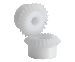
| Toothed Portion Shape: | Bevel Wheel |
| Material: | Cast Steel |
| Customization: |
Available
| Customized Request |
|---|
How do you ensure proper alignment when connecting miter gears?
Proper alignment is crucial when connecting miter gears to ensure smooth and efficient power transmission. Here are some key steps to ensure proper alignment:
- Shaft Alignment: Start by ensuring that the shafts on which the miter gears are mounted are properly aligned. Misalignment of the shafts can lead to increased friction, premature wear, and reduced efficiency. Use alignment tools such as dial indicators or laser alignment systems to accurately align the shafts.
- Gear Positioning: Position the miter gears in such a way that their axes intersect at a 90-degree angle. This ensures proper meshing of the gears and optimal power transmission. Pay attention to the position of the gears and make any necessary adjustments to achieve the desired alignment.
- Bearing Support: Proper bearing support is essential for maintaining alignment and reducing excessive loading on the gears. Ensure that the bearings supporting the shafts are accurately installed and aligned. Use high-quality bearings suitable for the load and speed requirements of the miter gears.
- Clearance and Backlash: Check for proper clearance and backlash between the teeth of the miter gears. Clearance refers to the space between the mating teeth, while backlash is the amount of play or movement between the gears. Proper clearance and backlash allow for smooth engagement and disengagement of the gears without binding or excessive noise.
- Lubrication: Apply a suitable lubricant to the miter gears to reduce friction and wear. Proper lubrication ensures smooth operation and helps maintain alignment by minimizing heat buildup and preventing excessive wear on the gear teeth.
By following these steps, you can ensure proper alignment when connecting miter gears, resulting in efficient power transmission, reduced wear, and improved overall performance.

How do you calculate the gear ratio in a miter gear assembly?
The gear ratio in a miter gear assembly can be calculated by considering the number of teeth on the gears involved. Here’s a step-by-step explanation:
1. Determine the Number of Teeth:
Identify the number of teeth on both the driving gear (input gear) and the driven gear (output gear) in the miter gear assembly. The number of teeth can usually be found in the gear specifications or by physically counting the teeth.
2. Calculate the Gear Ratio:
To calculate the gear ratio, divide the number of teeth on the driven gear (output gear) by the number of teeth on the driving gear (input gear). The formula for calculating the gear ratio is:
Gear Ratio = Number of Teeth on Driven Gear / Number of Teeth on Driving Gear
3. Simplify the Ratio (Optional):
If the resulting gear ratio is a fraction, it can be simplified to its simplest form. Divide both the numerator and the denominator by their greatest common divisor to simplify the ratio.
4. Interpret the Gear Ratio:
The gear ratio indicates the relationship between the rotational speed or angular velocity of the driving gear and the driven gear. It represents how many times the driven gear rotates for each rotation of the driving gear. For example, a gear ratio of 2:1 means that the driven gear rotates twice for every rotation of the driving gear.
5. Consider the Significance:
The gear ratio has practical implications in determining the mechanical advantage and speed reduction/amplification in a miter gear assembly. A gear ratio greater than 1 indicates a speed reduction and increased torque, while a gear ratio less than 1 indicates a speed amplification and decreased torque.
In summary, the gear ratio in a miter gear assembly is calculated by dividing the number of teeth on the driven gear by the number of teeth on the driving gear. This ratio represents the relationship between the rotational speeds of the gears and provides insights into the mechanical advantage and speed transformation in the gear assembly.
What are the advantages of using miter gears in machinery?
Miter gears offer several advantages when used in machinery. Here’s a detailed explanation of their advantages:
1. Right Angle Power Transmission:
One of the primary advantages of miter gears is their ability to transmit power between intersecting shafts at a right angle. This allows for efficient power transfer in machinery where the input and output shafts need to be oriented perpendicularly. Miter gears eliminate the need for additional components or complex mechanisms to achieve this right angle power transmission.
2. Compact Design:
Miter gears have a compact design due to their conical shape and intersecting shaft arrangement. They occupy less space compared to other types of gears used for parallel or non-intersecting shafts. This compactness is particularly beneficial in machinery where space constraints are a concern, allowing for more efficient utilization of available space.
3. Directional Change of Rotation:
Miter gears enable the change in the direction of rotational motion. By meshing two miter gears, the input rotational motion can be redirected at a 90-degree angle. This flexibility in changing the direction of rotation is advantageous in machinery that requires precise control over the direction of movement or where space limitations restrict the orientation of the equipment.
4. Speed Adjustment:
Miter gears can be used to achieve speed reduction or increase by varying the number of teeth on the gears or combining them with other gears. This allows for adjusting the rotational speed to match the desired output speed. The ability to change the speed with miter gears provides flexibility in adapting the machinery to specific operational requirements.
5. Smooth Operation:
When designed and manufactured with precision, miter gears can provide smooth and efficient operation. Proper tooth profile and tooth contact ensure minimal noise and vibration during gear engagement, resulting in quieter and more reliable machinery performance.
6. Versatility:
Miter gears are versatile and find applications in a wide range of machinery across various industries. They can be employed in different types of equipment, including mechanical clocks, robotics, printing machinery, automotive differentials, camera lenses, and more. The versatility of miter gears makes them a valuable choice for different machinery requirements.
7. High Torque Transmission:
Miter gears are capable of transmitting high torque due to their robust construction and tooth engagement characteristics. This makes them suitable for machinery that requires the transmission of substantial power or torque, ensuring reliable operation even under demanding conditions.
In summary, the advantages of using miter gears in machinery include right angle power transmission, compact design, directional change of rotation, speed adjustment, smooth operation, versatility, and high torque transmission. These advantages make miter gears a preferred choice in various machinery applications, offering efficiency, flexibility, and reliable performance.


editor by CX 2024-03-26