Product Description
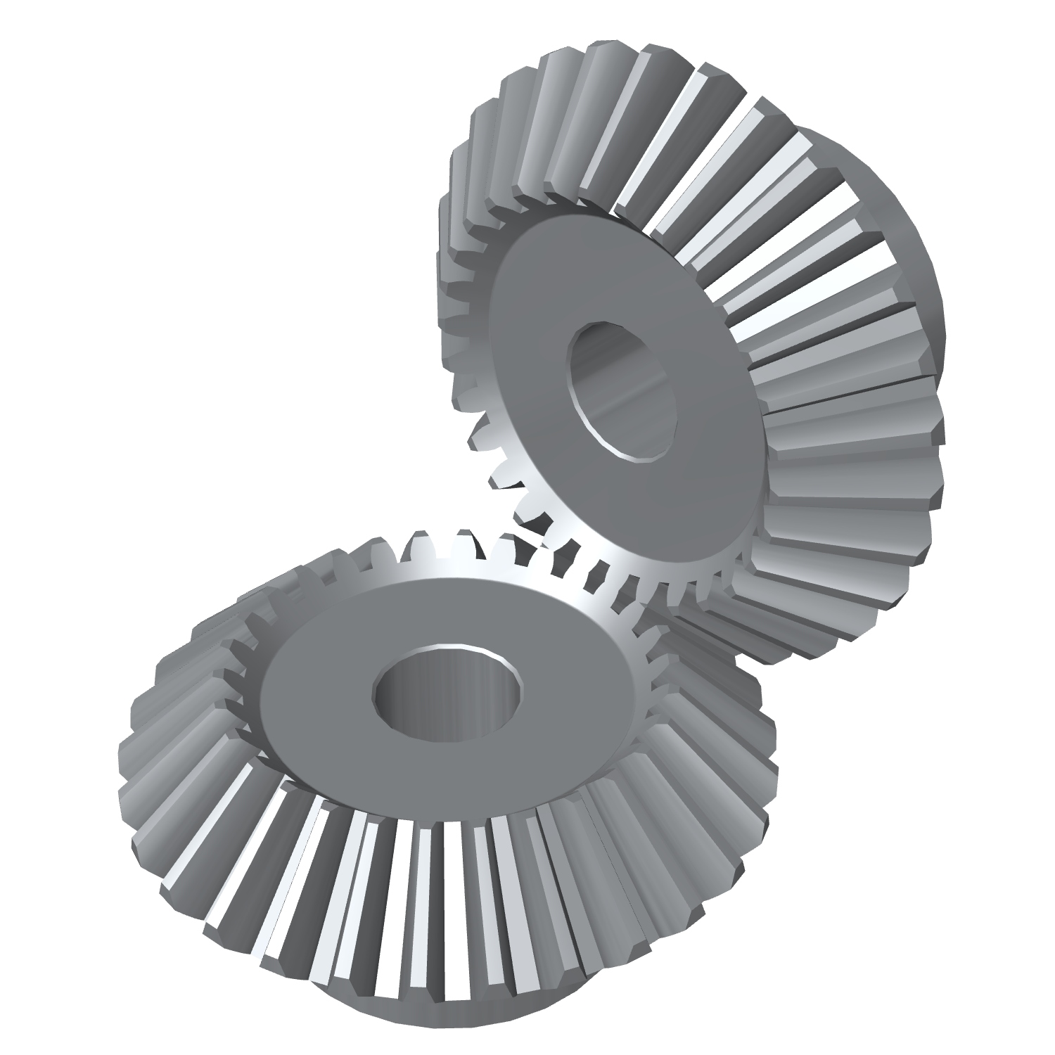
Stainless Steel Bevel Gears 90 Degree Miter Spiral Best Supplyer Forged Plastic Sintered Metal High Quanlity CHINAMFG for Test Machine Stainless Steel Bevel Gears
Application of Bevel Gears
Bevel gears are used in a wide variety of applications, including:
- Automotive: Bevel gears are used in automotive differentials, steering gears, and transmissions.
- Machine tools: Bevel gears are used in machine tools, such as lathes and milling machines, to transmit power from the motor to the cutting tool.
- Aerospace: Bevel gears are used in aerospace applications, such as jet engines and helicopters.
- Robotics: Bevel gears are used in robotics, such as robotic arms and manipulators.
- Industrial machinery: Bevel gears are used in industrial machinery, such as conveyor belts and pumps.
Bevel gears are a type of gear with teeth that are cut at an angle to the axis of rotation. This angle creates a gradual meshing of the teeth, which results in smoother operation and less noise than other types of gears, such as spur gears. Bevel gears also have a higher efficiency than spur gears, which means that they can transmit more power with less loss.
Here are some of the specific benefits of using bevel gears:
- Smoother operation: Bevel gears have a smoother operation than other types of gears, which makes them a good choice for applications where noise and vibration are a concern.
- Less noise: Bevel gears produce less noise than other types of gears, which makes them a good choice for applications where noise is a concern.
- Higher efficiency: Bevel gears have a higher efficiency than other types of gears, which means that they can transmit more power with less loss.
- Longer life: Bevel gears have a longer life than other types of gears, which makes them a good choice for applications where durability is a concern.
Bevel gears are a versatile and essential part of many machines and systems. They are used to transmit power and motion between different components, and they offer a number of advantages over other types of gears, such as smooth operation, less noise, higher efficiency, and longer life.
Here are some examples of how bevel gears are used in specific applications:
- Automotive: Bevel gears are used in automotive differentials to transmit power from the driveshaft to the wheels.
- Machine tools: Bevel gears are used in machine tools, such as lathes and milling machines, to transmit power from the motor to the cutting tool.
- Aerospace: Bevel gears are used in aerospace applications, such as jet engines and helicopters, to transmit power from the engine to the propeller or rotor.
- Robotics: Bevel gears are used in robotics, such as robotic arms and manipulators, to transmit power from the motor to the joints.
- Industrial machinery: Bevel gears are used in industrial machinery, such as conveyor belts and pumps, to transmit power from the motor to the drive shaft.
Bevel gears are a versatile and essential part of many machines and systems. They are used to transmit power and motion between different components, and they offer a number of advantages over other types of gears, such as smooth operation, less noise, higher efficiency, and longer life.
| Application: | Motor, Electric Cars, Motorcycle, Machinery, Marine, Toy, Agricultural Machinery, Car |
|---|---|
| Hardness: | Hardened Tooth Surface |
| Gear Position: | Internal Gear |
| Manufacturing Method: | Cast Gear |
| Toothed Portion Shape: | Worm Gear |
| Material: | Stainless Steel |
| Samples: |
US$ 9999/Piece
1 Piece(Min.Order) | |
|---|
What are the limitations of using miter gears in certain applications?
Miter gears, like any other mechanical component, have certain limitations that may restrict their use in certain applications. While miter gears are versatile and widely used, it’s important to consider their limitations to ensure proper selection and application. Here are some limitations of using miter gears:
- Higher Friction: Miter gears typically have higher friction compared to other types of gears, such as spur gears or helical gears. This can result in increased power losses and reduced efficiency, especially in applications where minimizing friction is critical.
- Lower Load Capacity: Miter gears generally have a lower load-carrying capacity compared to gears with parallel or helical tooth arrangements. The nature of their intersecting shafts and smaller tooth engagement area can limit their ability to handle heavy loads or transmit high torque.
- Sensitivity to Misalignment: Miter gears require precise alignment for optimal performance. Even slight misalignment between the shafts can result in increased noise, vibration, and accelerated wear. In applications where maintaining precise alignment is challenging, alternative gear types may be more suitable.
- Limited Speed Range: Miter gears may have limitations in terms of the speed range they can effectively operate at. High speeds can lead to increased noise, heat generation, and potential tooth failure due to centrifugal forces. It’s essential to consider the specific speed requirements of the application and select gears accordingly.
- Complex Manufacturing: Miter gears with specific angles, such as non-90-degree gears, require more complex manufacturing processes compared to standard 90-degree miter gears. This complexity can result in higher costs and longer lead times for custom or non-standard gear configurations.
Despite these limitations, miter gears continue to be widely used in various applications where their unique characteristics and advantages outweigh the drawbacks. It’s important to carefully evaluate the specific requirements of the application and consider alternative gear options if the limitations of miter gears pose significant challenges.

How do you calculate the gear ratio in a miter gear assembly?
The gear ratio in a miter gear assembly can be calculated by considering the number of teeth on the gears involved. Here’s a step-by-step explanation:
1. Determine the Number of Teeth:
Identify the number of teeth on both the driving gear (input gear) and the driven gear (output gear) in the miter gear assembly. The number of teeth can usually be found in the gear specifications or by physically counting the teeth.
2. Calculate the Gear Ratio:
To calculate the gear ratio, divide the number of teeth on the driven gear (output gear) by the number of teeth on the driving gear (input gear). The formula for calculating the gear ratio is:
Gear Ratio = Number of Teeth on Driven Gear / Number of Teeth on Driving Gear
3. Simplify the Ratio (Optional):
If the resulting gear ratio is a fraction, it can be simplified to its simplest form. Divide both the numerator and the denominator by their greatest common divisor to simplify the ratio.
4. Interpret the Gear Ratio:
The gear ratio indicates the relationship between the rotational speed or angular velocity of the driving gear and the driven gear. It represents how many times the driven gear rotates for each rotation of the driving gear. For example, a gear ratio of 2:1 means that the driven gear rotates twice for every rotation of the driving gear.
5. Consider the Significance:
The gear ratio has practical implications in determining the mechanical advantage and speed reduction/amplification in a miter gear assembly. A gear ratio greater than 1 indicates a speed reduction and increased torque, while a gear ratio less than 1 indicates a speed amplification and decreased torque.
In summary, the gear ratio in a miter gear assembly is calculated by dividing the number of teeth on the driven gear by the number of teeth on the driving gear. This ratio represents the relationship between the rotational speeds of the gears and provides insights into the mechanical advantage and speed transformation in the gear assembly.
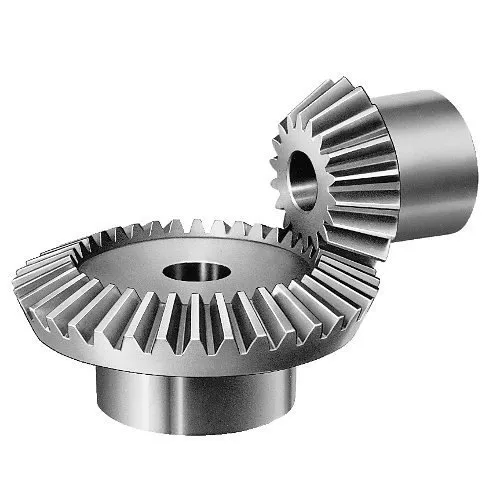
Can you explain the unique design of miter gear teeth?
The design of miter gear teeth is distinct and plays a crucial role in the functionality of these gears. Here’s a detailed explanation:
1. Tooth Shape:
Miter gear teeth have a straight shape, similar to spur gears. However, unlike spur gears where the teeth are parallel to the gear axis, miter gear teeth are cut at a right angle to the gear’s face. This allows the teeth to engage correctly when two miter gears mesh together at a 90-degree angle.
2. Equal Number of Teeth:
Miter gears have an equal number of teeth on both gears in a pair. This ensures proper meshing and smooth transmission of rotational motion between the gears. The equal number of teeth is essential for maintaining a constant speed ratio and preventing any slippage or irregular motion.
3. Conical Shape:
Another unique aspect of miter gear teeth is the conical shape of the gears themselves. The teeth are cut on the conical surface, which allows for proper engagement and transmission of motion between intersecting shafts. The conical shape ensures that the teeth mesh correctly, providing efficient power transmission at the desired angle.
4. Meshing at 90-Degree Angle:
Miter gears are designed to mesh at a 90-degree angle, allowing for power transmission between intersecting shafts. The teeth are specifically cut to facilitate this arrangement, ensuring that the gears engage smoothly and transmit rotational motion without any loss or disruption.
5. Tooth Contact and Load Distribution:
When miter gears mesh, the contact between the teeth occurs along a single line, known as the line of contact. This concentrated contact area enables effective load distribution and ensures that the gear teeth bear the transmitted torque evenly. Proper tooth contact is vital for minimizing wear and maintaining the longevity of the gears.
6. Lubrication and Noise Reduction:
The unique design of miter gear teeth can influence lubrication and noise levels. Adequate lubrication is essential to reduce friction and wear between the teeth during operation. Additionally, the straight tooth profile of miter gears tends to produce more noise compared to gears with helical or curved teeth. Proper lubrication and noise reduction measures are often employed to optimize the performance of miter gears.
In summary, the unique design of miter gear teeth includes their straight shape, equal number of teeth, conical shape of the gears, meshing at a 90-degree angle, tooth contact along a line, and considerations for lubrication and noise reduction. These design features ensure efficient power transmission, proper load distribution, and reliable operation in mechanical systems that utilize miter gears.


editor by CX 2023-09-28